Building a Carbon Fiber RC Plane (737) – Turning Digital Design into Reality

Figure 1 – From CAD model to carbon fiber part


Click here to read the first part of the series covering the design and CAD modeling process


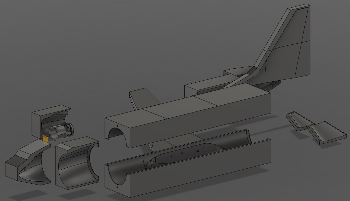
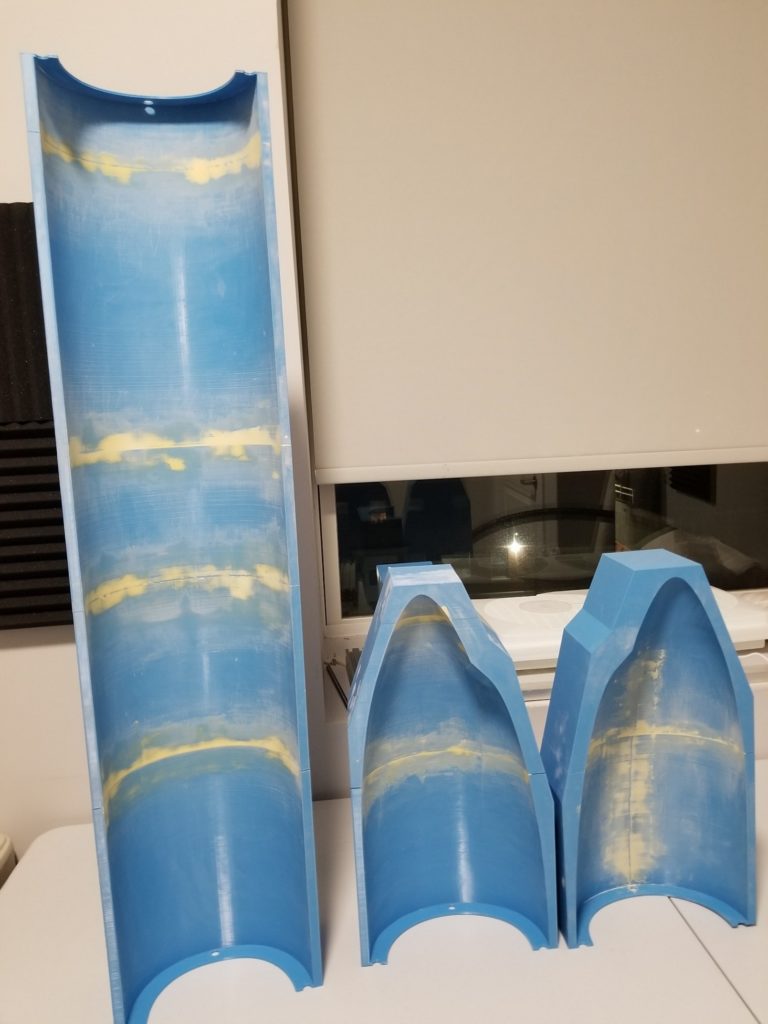
With the CAD modeling of the Boeing 737 complete, the next step was to turn the digital model into reality! To do this, I first created moulds that have the negative shape of the plane (Figure 2) in Fusion 360 by using tools, such as extrusion and cut. Once that was complete, I used my 3D printer, Creality Cr-10 V2, to print these moulds. A video example is shown in Figure 3. The moulds were cut into the sizes shown in Figure 2 to ensure the dimensions are less than the maximum printing volume of the 3D printer (30 cm x 30 cm x 40 cm).


Figure 2 – CAD modelled moulds

Figure 3 – 3D printing the mould for the vertical stabilizer


The 3D printed moulds were glued together by sections (i.e. the moulds for the nose were glued separately from the main fuselage and so on) and gaps filled in with wood filler. The wood filler was then dry sanded in order to level the surface. An example of this is shown in Figure 4.


Figure 4 - Glued and dry sanded main fuselage and nose moulds

To prepare the moulds for the carbon fiber wet layup, I sprayed the cavities with filler primer. Once that was dried, I wet sanded the cavities using 800 grit sand paper to ensure the surfaces were smooth. Afterwards, I applied three layers of mould release wax and two layers of polyvinyl alcohol (PVA) based mould release agent. Figure 5 shows the moulds for the nose and main fuselage with these steps completed.


Figure 5 - Nose and main fuselage moulds with final layer of PVA release agent applied

For the wet layup, I am using 100 grams/squared meter (gsm) fiber glass as my first layer, 240 gsm carbon fiber as my second layer, peel ply as my third layer, breather fabric as my fourth layer, Aeropoxy PR2032 epoxy resin, and Aeropoxy PH3663 hardener. The process I generally follow when performing a wet layup is the following:


    1. Cut the fiber glass, carbon fiber, peel ply, and breather fabric down to size
    2. Weigh the fiber glass and carbon fiber and produce the same amount (in mass) of epoxy  (ex. 100 grams of fiber glass and carbon fiber requires 100 grams of epoxy)
    3. Apply an initial layer of epoxy onto the cavity surface
    4. Place a layer of the fiber glass onto the cavity surface and press the fabric down until there is no visible gap between the fabric and the cavity surface. Cut out any excess fabric
    5. Apply a second layer of epoxy on top of the fiber glass
    6. Place a layer of the carbon fiber onto the surface and press the fabric down until there is no visible gap between the fabric and layer below it. Cut out any excess fabric
    7. Apply a third layer of epoxy on top of the carbon fiber
    8. Place a layer of peel ply onto the surface and press the fabric down until there is no visible gap between the peel ply and the fabric layer below it
    9. Place a layer of breather fabric on top of the peel ply
    10. Carefully place the part inside a vacuum bag and close the bag tightly shut
    11. Remove as much air out of the bag as possible using a vacuum cleaner
    12. Leave the part to cure for 1 to 2 days
Figure 6 - After placing a layer of peel ply and before placing a layer of breather fabric
Figure 7 - Part of the tail piece vacuum bagged in a Space Saver bag
Figure 8 - My friend joining me in creating the tail piece (looking like two big marshmallows)
Figure 9 - My friend looking very proud of his work

The end result looks something like the examples shown in Figures 10 and 11.


Figure 10 - Right side nose
Figure 11 - Left side tail

So far, I’ve completed the nose, the top main fuselage, and the tail sections. In the next post, I will go over the wet layup process for the rest of the plane (bottom fuselage and the wings).