Introduction
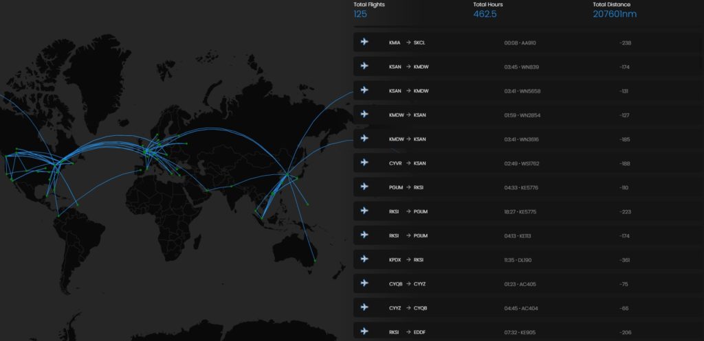
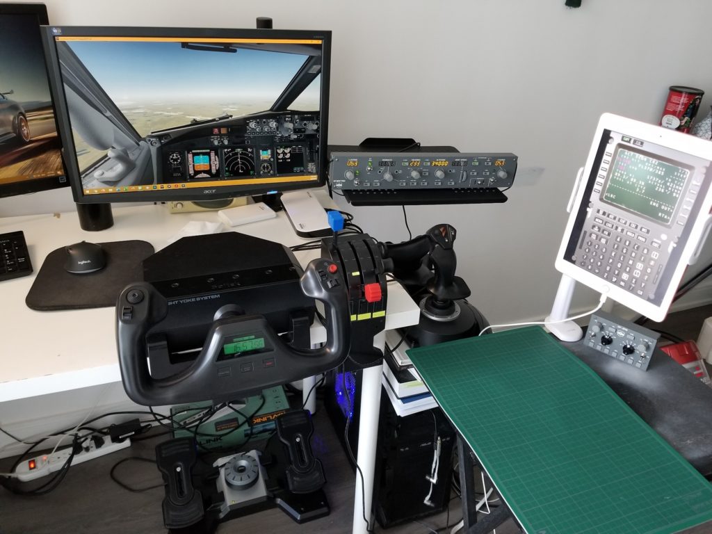
Ever since I was little, I have had a strange obsession over commercial airplanes… Ask anyone close to me; they’ll tell you! As much I love engineering, I’ve always wanted to be a pilot (and I still do). I love to spend hours flying planes virtually on flight simulator planning and flying real routes following real checklists. Since January 2020, I’ve logged 460 hours of flying time. But I’m pretty sure I have flown thousands of hours virtually since I started this hobby back in 2008.
Designing & CAD Modeling
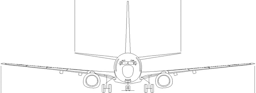
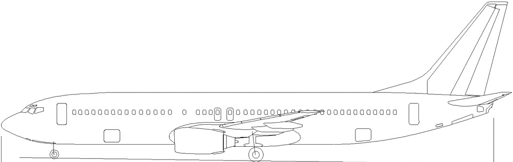
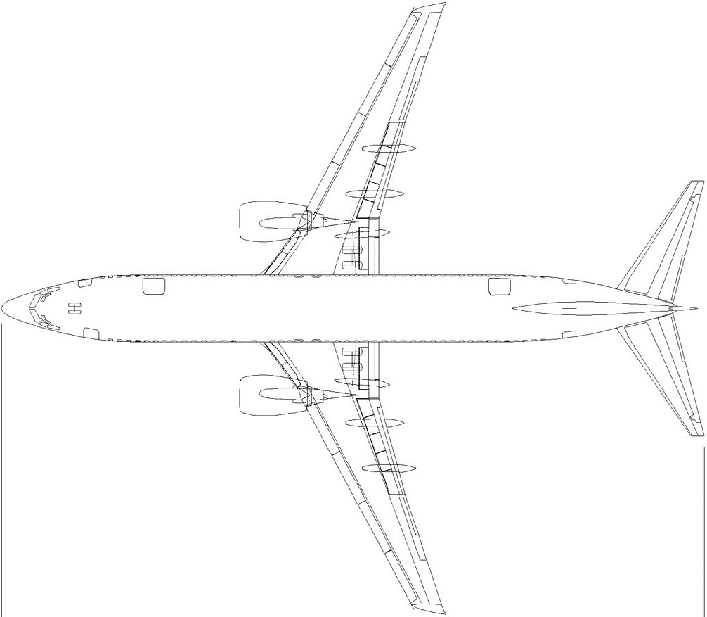
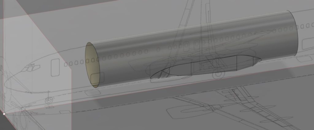
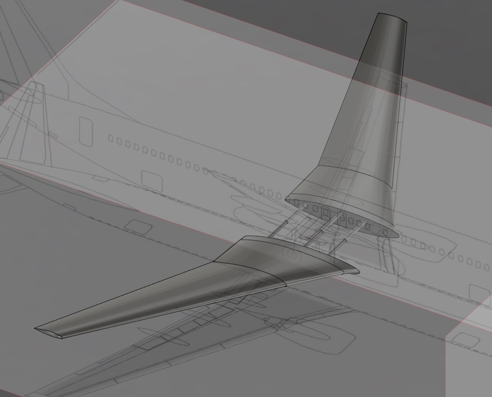
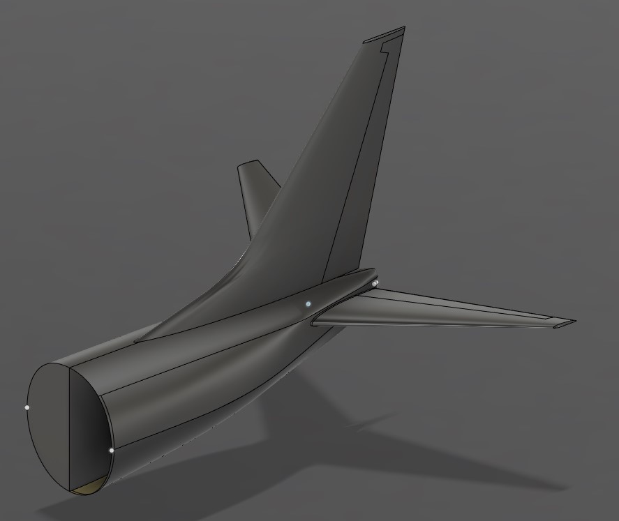
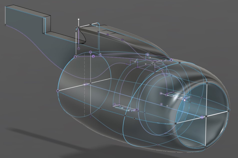
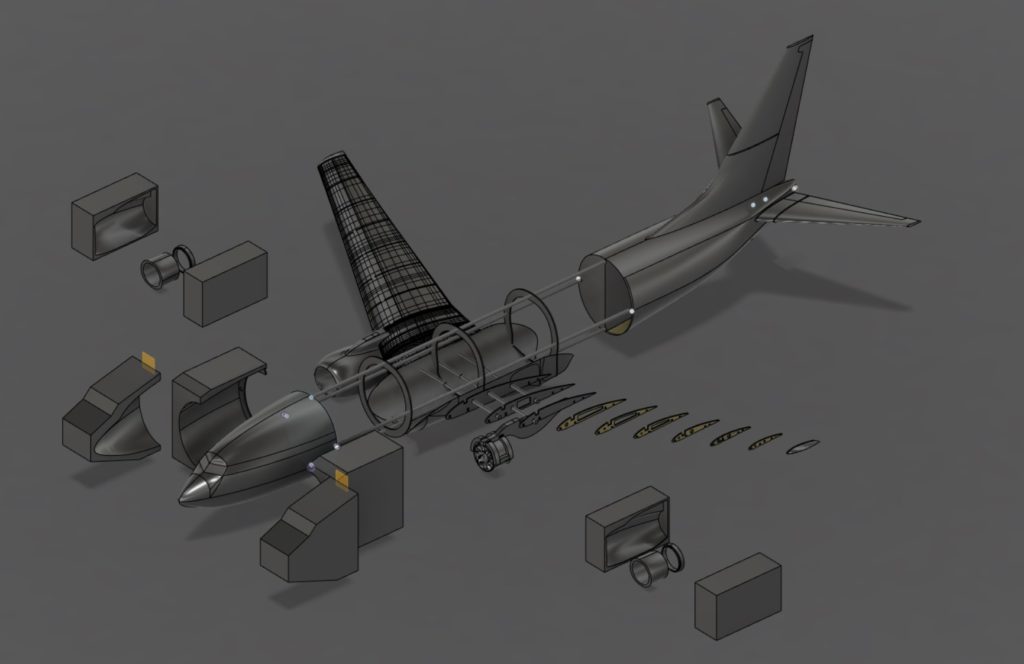
To CAD model the airplane, I used Autodesk Fusion 360 because it has many of the features available in higher end CAD programs, such as SolidWorks, and most importantly can easily produce and convert toolpaths for my mini CNC milling machine to create various structural components (i.e. ribs, spars, and landing gear platforms) out of Birchwood plywood. I used the front, side, and top view drawings of a 737-800 (Figures 3 to 5) as my canvases.
Wing Airfoil Design
The wing was one of the most challenging parts to design as I had to not only select airfoils that can provide good lift and predictable characteristics, but also mimic the original design of the 737 wing as closely as possible AND provide enough room for landing gears, servos for flaps and ailerons, ribs, spars, and wires.
At first, I used the real airfoils used in the 737 for the wings (Figure 12). All the airfoils described in this post were obtained from airfoiltools.com.
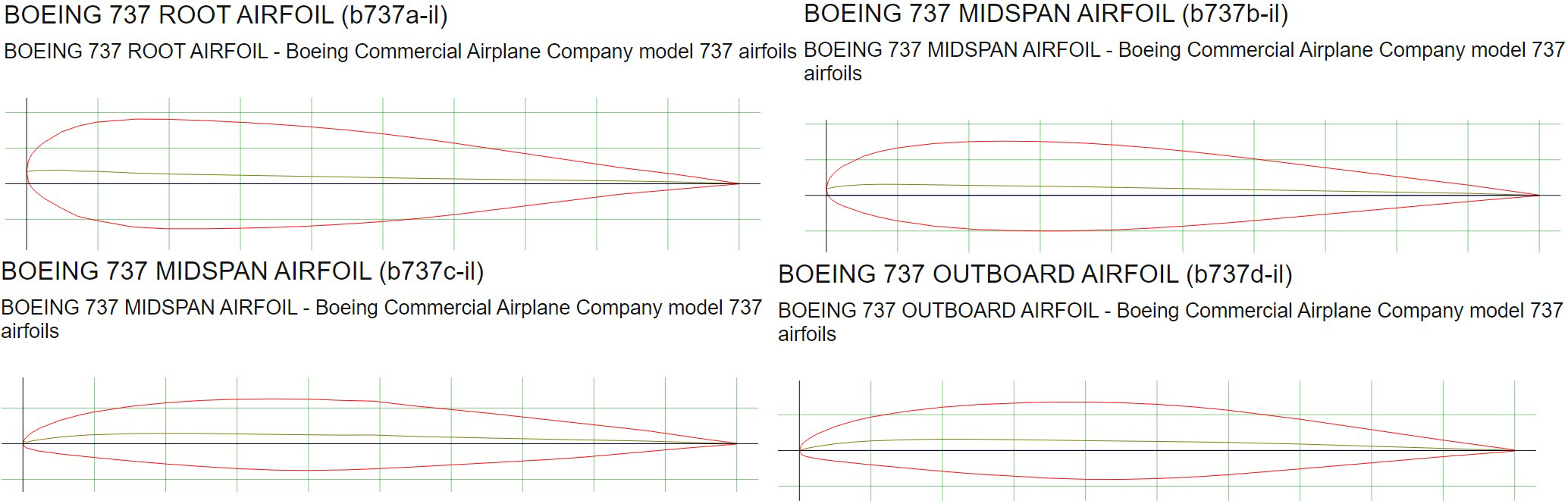
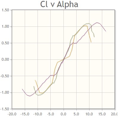
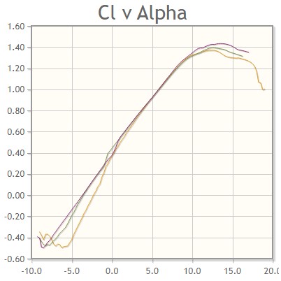
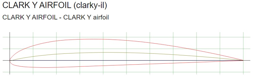
However, after studying the polar plot charts of lift coefficient for these and other airfoils, I realized that I wasn’t going to get the lift characteristics I was aiming for at the speed and pitch the plane was intended to fly at using the real airfoils. A polar plot chart of lift coefficient is a chart that plots the lift force per unit span of a wing against the angle of attack (the angle between the chord line of the airfoil and the direction of oncoming air). Figure 13 shows the polar plot charts for the real 737 airfoils. Figure 14 shows the polar plot chart for an airfoil called CLARK Y (Figure 15), which is a commonly used airfoil in RC model aircrafts.
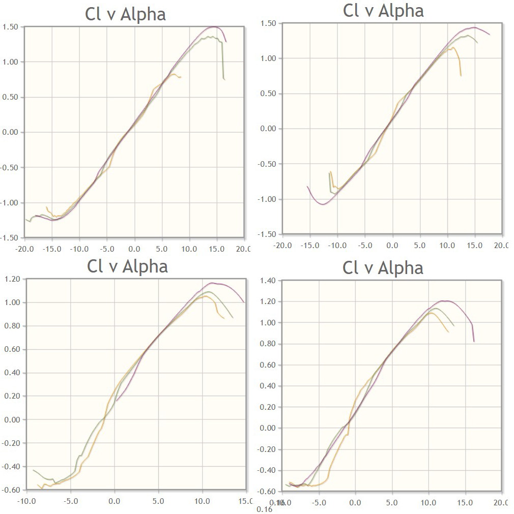
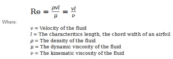
The three lines on each plot represent the relationship between the lift coefficient and the angle of attack at three different Reynolds number. The Reynolds number is a dimensionless value that measures the ratio of inertial forces to viscous forces and describes the degree of laminar or turbulent flow. The equation is shown in Figure 16. Assuming the plane flies through 20 degrees Celsius air with a velocity between 10 m/s and 30 m/s, that gives us a Reynolds number range of 100,000 to 500,000. The brown, green, and purple lines represent Reynolds number of 100,000, 200,000, and 500,000, respectively.
At a 0 degree angle of attack, the real 737 airfoils generate around 0.10 to 0.20 lift force per unit span of the wing, whilst the CLARK Y airfoil generates around 0.40 lift force. This means that wings that use the CLARK Y airfoil produces more lift than the real 737 airfoils, which is crucial to ensure the RC plane can takeoff and remain airborne at a lower and sustainable pitch. Moreover, the lift coefficient for the CLARK Y airfoil drops off at an angle of attack similar to that of the real 737 airfoils. This means the CLARK Y airfoil has similar gentle stall characteristics of a real 737.
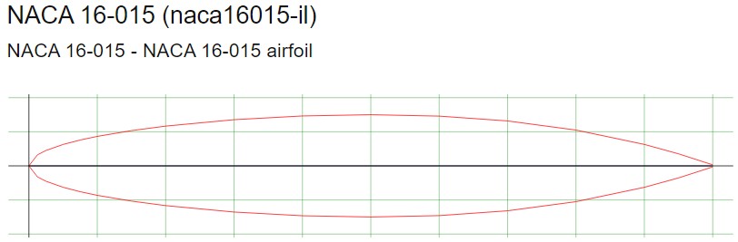
Feeling confident with the CLARK Y airfoil, I proceeded to use this airfoil to redesign the wing and the wing box. But it was not long before I realized this airfoil was too thin to house the landing gear… Back to the drawing board! After searching through countless airfoils, I found one that I could use as the root airfoil that provides enough room for the landing gear and servos: NACA 16-015 (Figure 17).
Although this design provides the necessary internal space, the polar plot chart of lift coefficient is… far from ideal. As shown in Figure 18, the lift coefficient is zero when the angle of attack is zero. And at lower speeds, the lift coefficient drop-off occurs much sooner than all the other airfoils…