When you go to a grocery store and use a shopping cart, you probably don’t think twice about the design of the shopping cart and the engineering that goes behind one, do you? Well frankly, I don’t either… That’s because they just work! They are so robustly designed to take on heavy payloads in various conditions in almost every way the user may use them that they’re easily taken for granted.
In my 4th year Machine Design course at the University of Toronto, I was tasked on tackling this exact challenge for my own shopping cart design. I was to design one that can carry a payload of 100 kg and go up and down a curb at a regular walking speed without any structural issues. I took inspiration from various readily available shopping cart designs to obtain rough dimensions and came up with the following design in SolidWorks.
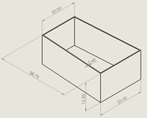
▲ Figure 1 - Basket
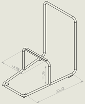
▲ Figure 2 - Cart frame
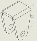
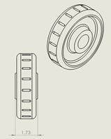
▲ Figure 3 - Wheel flange
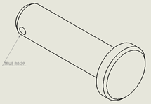
▲ Figure 4 - Axle (Pin)
▲ Figure 5 - Cart wheel
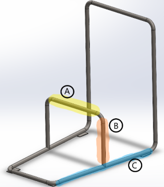
Engineering analyses were performed on the cart frame (Figure 2) and the wheel axle (Figure 4) because they were identified to likely fail before the other components of the shopping cart do. The cart frame was broken down into three sections (or beams) for the analyses as shown in Figure 6.
▲ Figure 6 - Sections of cart frame
To determine whether the shopping cart will function properly and safely, the following design analyses were performed on the aforementioned key areas through analytical calculations and finite element analysis. Finite element analysis was performed on ANSYS. SolidWorks Motion Analysis was used to obtain the reaction forces for the calculations.
Beam A
Max bending stress due to the distributed loading from the cart loading
Max deflection due to the distributed loading from the cart loading
Beam B
Buckling due to the loading from the basket
Beam C
Max stresses that occur stationary, going up the curb, and going down the curb
Max deflections that occur stationary, going up the curb, and going down the curb
Buckling due to the impact of hitting the curb while going up
Wheel Axle (Pin)
Double shear
Bearing load
Tear out stress
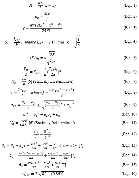
The following equations shown in Figure 7 were used in the analyses. The descriptions for them are below the figure.
▲ Figure 7 - Formulae used in the analytical calculations
Eqn. 1 – Moment equation for a simply supported beam
Eqn. 2 – Bending stress equation
Eqn. 3 – Deflection equation for simply supported beam
Eqn. 4 – Slenderness ratio for buckling analysis
Eqn. 6 – Johnson equation for buckling analysis
Eqn. 7 – Moment equation for statically indeterminate beams
Eqn. 8 – Shear stress due to torsion
Eqn. 9 – Principle stress equation
Eqn. 10 – Von Mises effective stress equation
Eqn. 11 – Deflection for statically indeterminate beams
Eqn. 12 – Euler equation for buckling analysis
Eqn. 13 – Beam deflection equation
Eqn. 14 – Beam deflection equation
Eqn. 15 – Beam deflection equation
Eqn. 16 – Tear out equation
Results and Future Improvements
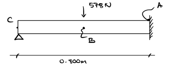
Based on the quality of the available material-property data, the potential environmental conditions in which the shopping cart may be exposed to, and the quality of the simulated models, an ideal safety factor (FOS) was determined to be 3. However in both the analytical and finite element analyses, the area in which failure could potentially occur was identified to be the bottom surface below point A of beam C (shown in Figure 8) when the shopping cart goes down the curb with the 100 kg load. The maximum Von Mises stress at that point was found to be 13 times the ultimate tensile strength of the material used, which was galvanized steel tube (low carbon). Therefore, the first potential improvement that can be done on the design is to redesign that area and possibly use stronger material and use wider and thicker tubes for the frame.
▲ Figure 8 - Beam C represented as a statically indeterminate beam
Another possible area of improvement is the design of the axle (pin). Although the analytical calculations showed that the current design is above the desired FOS, FEA analysis identified that other stresses, such as bending stress due the gap between the wheel and the flange, could be adding additional stress to the part, causing the fatigue factor of safety (FFOS) to fall below one. This means that axle may not fail initially but may fail over time. Potential improvements to the design could be an axle with a larger diameter, stronger material of the axle, and reduce the gap between the wheel and the flange to eliminate potential occurrence of bending stress in the axle.
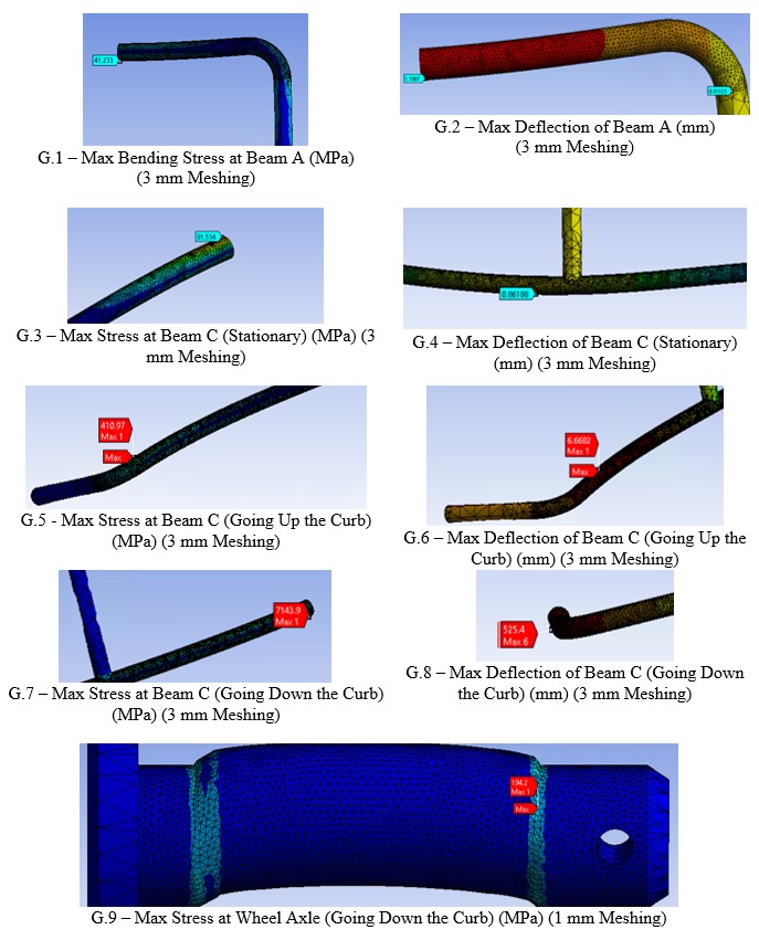
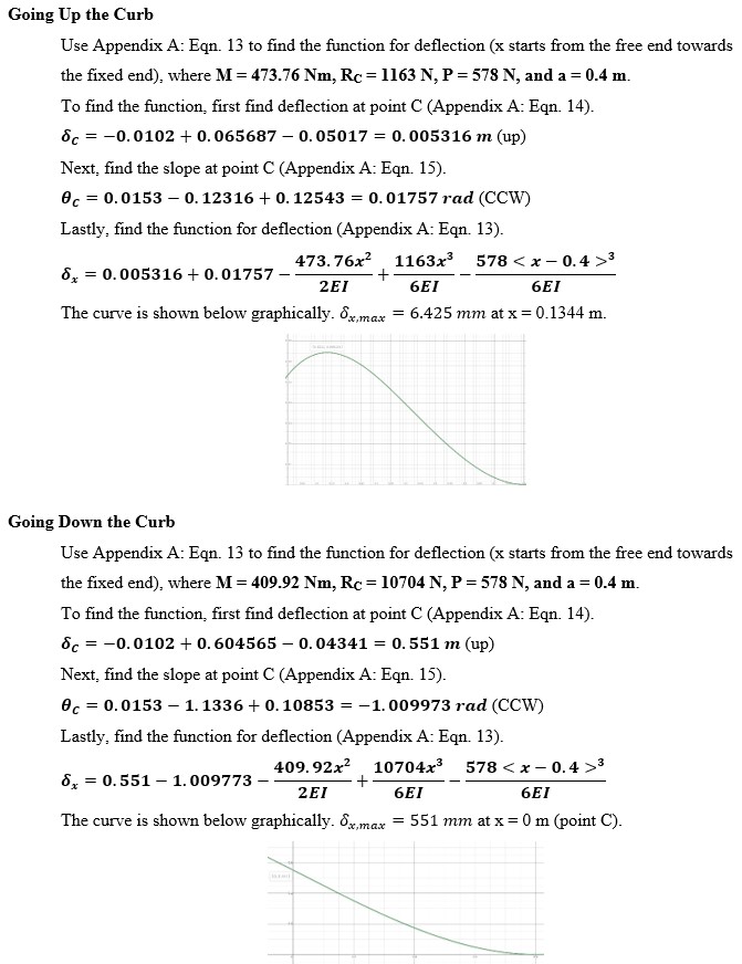
See Figures 9 and 10 below for relevant ANSYS FEA results and beam C deflection calculations, respectively.