GD&T Design Project: Jig & Fixture

Imagine you have multiple identical parts that require holes to be drilled at the same precise locations. How would you go about doing so? You can try and use a modern multi-axis CNC machine or a manual 3-axis machine. However, both of these methods require machines and highly skilled operators that can be prohibitively expensive to maintain. To lower operating and capital costs under most conditions, a simple single axis machine, such as a drill press, can be used with a well designed indexing jig and fixture that can produce multiple precisely located holes on parts repetitively at a fraction of the cost compared to the other methods.


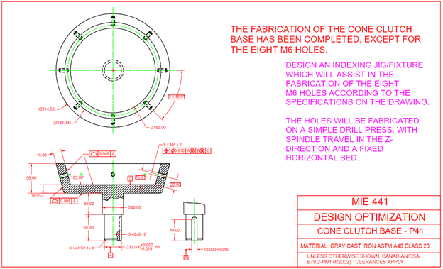
In a 4th year Design Optimization course at the University of Toronto, I was tasked with tackling this exact challenge – design an indexing jig and fixture to fabricate eight precisely located M6 holes on multiple identical cone clutch bases (shown in Figure 1).


Figure 1 – Cone clutch base
Watch the full detailed presentation of the project below that outlines the whole design process from start to finish. Tolerance stack-up analysis starts at 6:41, and the discussion on the areas of improvement begins at 8:07.
 

Description of Design

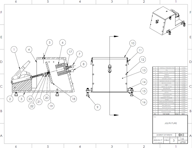
The design of the jig and fixture consists of the following major components shown in Figure 2: fixed/static backplate (13), indexing plunger (8), part holding module (6), “datum C plate” (18), and toggle clamp (1). The indexing plunger is fixed onto the backplate below the turning knob of the part holding module. The part holding module (PHM) is also integrated into the backplate and can rotate axially with respect to the backplate. The “datum C plate” attaches to one end of the toggle clamp shaft via a bearing (19), spring-loaded bearing-to-stud adaptor (21) and a partially threaded stud (23). The bearing allows the “datum C plate” to rotate about the same axis as the one the PHM rotates about. The toggle clamp facilitates the movement of the “datum C plate” along the axis of its rotation, allowing for the part to be “clamped” into position.


Figure 2 – Jig and fixture assembly section view

To position the part inside the jig/fixture, the part holding module was designed so that the datum feature A of the part (32mm diameter of the shaft) first mates with the inner bore of the part holding module (datum A simulator). The part slides down into the bore until it reaches a keyway where the datum feature B of the part (10mm wide notch) mates with the width of the key (datum B simulator). The part continues to slide down until it stops to where the shaft diameter steps up to 40 mm.


Once the part is positioned inside the part holding module, the perfectly flat side of the “datum C plate” (datum C simulator) mates with the datum feature C of the part (inner circular surface) with the use of the toggle clamp. The “datum C plate” then continues to gently apply some pressure towards the backplate to “clamp” and secure the part in place. The spring-loaded mechanism behind the “datum C plate” allows the plate to be pressed onto the datum feature C without requiring excessive force to lock the toggle clamp into position. Moreover, the plate is positioned in a manner that would always result in some compression in the spring to provide adequate pressure to the datum feature C to lock the part in place.


To fabricate the eight M6 holes on the part from the top, the part needs to be rotated axially and indexed at the correct positions. The part holding module can rotate axially and, therefore, rotate the part axially. The indexing is done by implementing the indexing plunger that has a spring-loaded pin that can “lock” into one of eight holes on the backside of the PHM. The part can be indexed to the next position by pulling on the plunger, allowing the pin to come out of the hole, and rotating the part holding module axially until the spring-loaded pin “locks” into the next adjacent hole of the backside of the PHM.