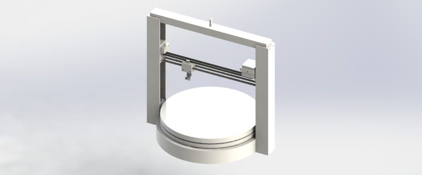
This original conceptual design of a 3D printer was created in a Mechanical Engineering Design course during second year (Fall 2017) of engineering. In a team of four, we were tasked on designing a kit-style 3D printer that can be used in a home or a small office setting.
Research was done on methods of 3D printing, current kit-style printers on the market, as well as materials used for printing. Using information from the original problem statement and research, an engineering specification was formed. The specification included functions, constraints, and objectives. Once that was completed, three candidate designs were generated shown in Figures 1, 2, and 3.
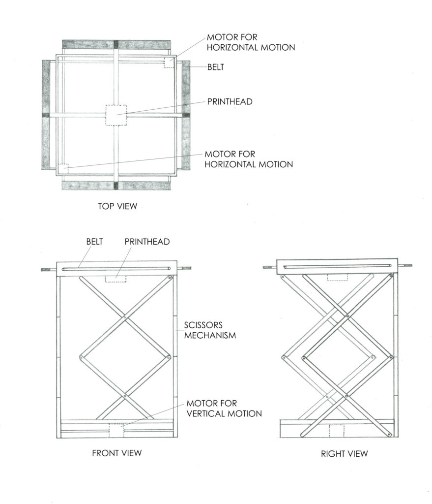
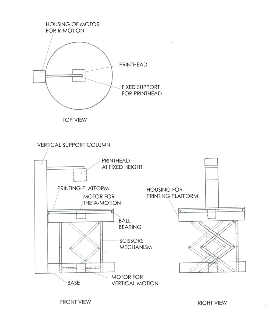
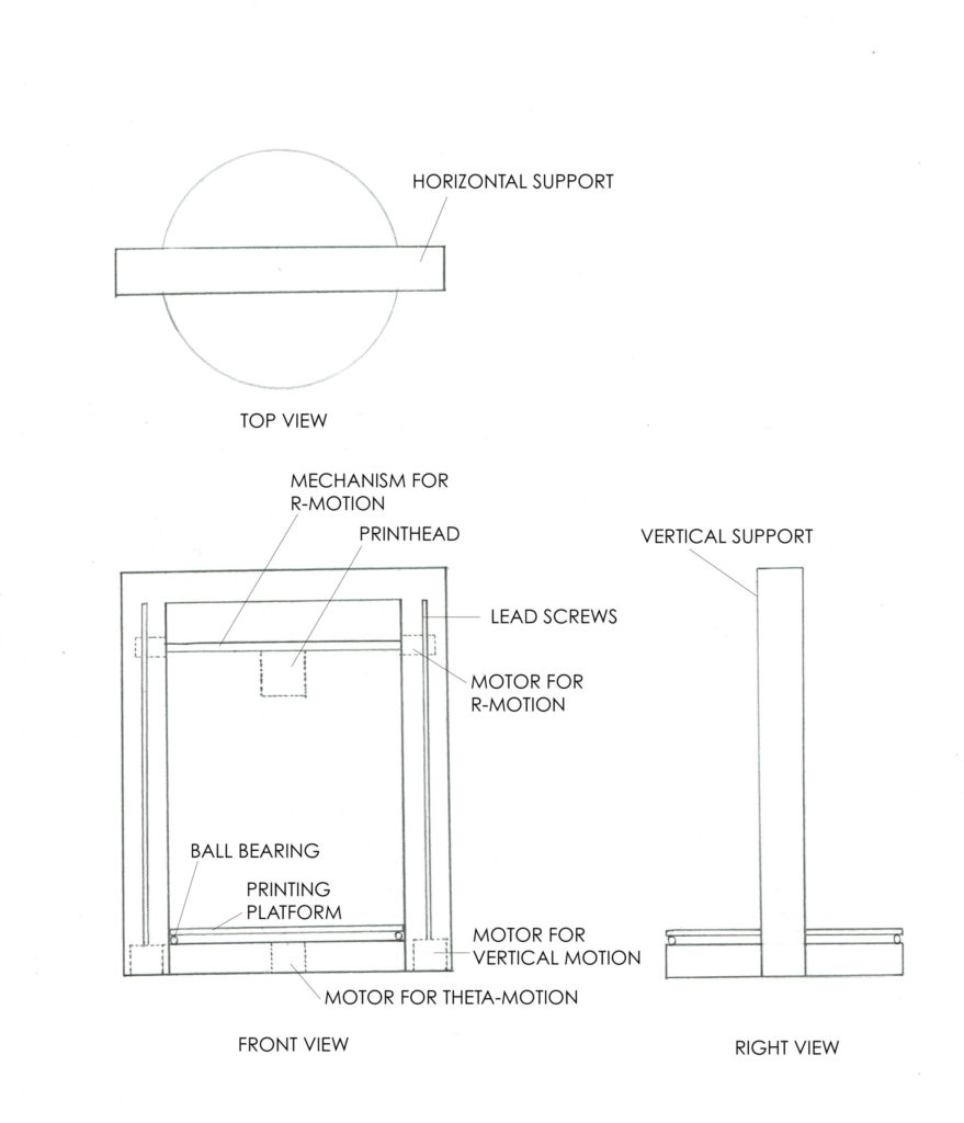
The three candidates were weighed against each other, and it was determined that the D-theta 3D printer was superior to the other two. This one has a rotating base powered by a directly attached motor which provides the theta-motion, a printhead mechanism that moves vertically facilitated by a pair of lead screws, and a printhead that moves horizontally using a belt drive and sliding rod combination.
The D-theta 3D printer design was created through a computed aided design (CAD) software called SolidWorks. Using the built-in addons, the material type for each part, from the motion mechanism, all the way to the screws for the whole assembly, were chosen. This allowed us to determine the overall cost of the assembly, which indicated it was much lower compared to the 3D printers in the market at the time.
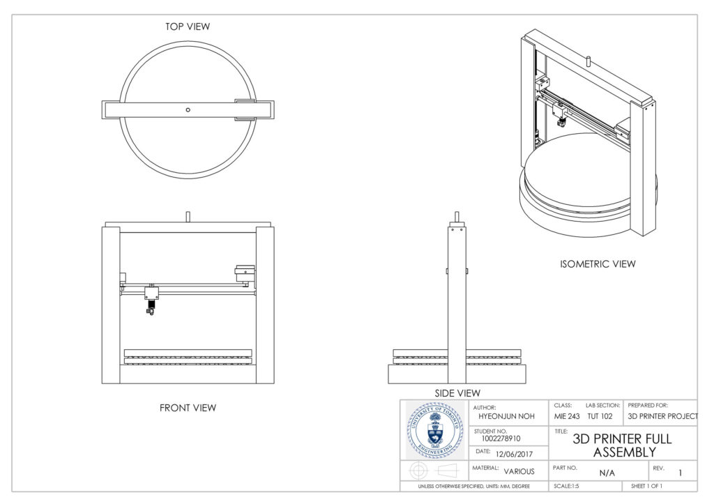
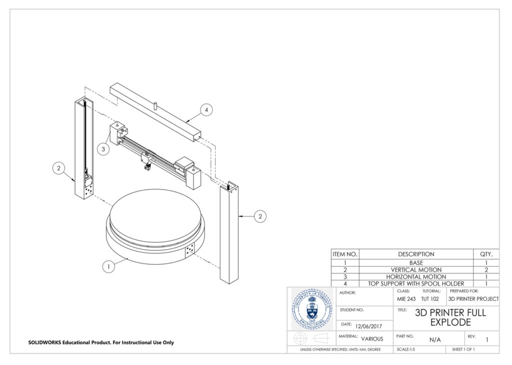
Overall, this project allowed us to utilize an engineering design process, generate our own creative ideas, create hand drawn engineering sketches, and work with SolidWorks to create a virtual preliminary 3D printer design which can be used to create a prototype using molds utilizing CNC.

